
Frieve Vinyl Explained Frieve Vinyl Explained
Frieve Vinyl Explained is an interactive WebGL simulation that shows how a record stylus traces a vinyl groove at microscopic scale. It lets you zoom from the overall groove shape down to nanometer-level motion while changing record, stylus, signal, and surface conditions. > Open App
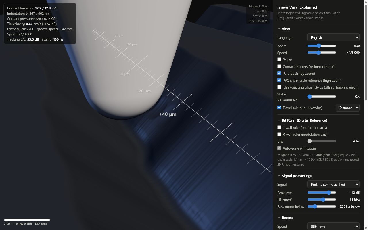
On first load, the app uses English unless your browser's primary language starts with Japanese. You can switch languages from the View panel.
Overview
The app visualizes the chain from mastered signal to groove wall movement, stylus contact, and playback output. The model uses real-world scale and units, so the controls are meant to feel like record and cartridge parameters rather than abstract animation settings.
The display is intentionally exaggerated only by zoom and slow motion. The stylus, groove, dust, contact markers, bit rulers, and measurement charts all refer to the same running simulation.
Launch the App
For Japanese UI, open:
Features
- Real-time 3D view of a stylus tracing a 45/45 vinyl groove.
- Zoom range from macroscopic groove motion down to nanometer-scale roughness.
- Signal controls for pink noise, sine waves, and silent-groove noise viewing.
- Record controls for RPM, groove radius, roughness, dust, scratches, and static.
- Stylus and cartridge controls for tip shape, radii, tracking force, tip mass, and compliance.
- Ideal-tracking ghost stylus that shows tracking error as a visible offset.
- Bit ruler overlays that compare groove-wall displacement with a digital quantization reference.
- Measurement panel for frequency response, noise spectrum, SNR, equivalent bits, THD, mistrack rate, and skip rate.
Main Controls
View
Use Zoom to move between overall groove shape, stylus contact, surface roughness, and molecular-scale references. Speed changes the slow-motion factor. Pause freezes the live view for inspection.
Signal
Choose pink noise for a music-like signal, sine wave for test tones, or silence to focus on surface noise. Peak level, high-frequency cutoff, and bass mono filtering change the groove modulation.
Record
RPM and groove radius affect groove speed. Roughness, dust, scratches, and static change the kinds of playback defects visible in the stylus motion and output measurements.
Stylus / Cartridge
Switch between elliptical and spherical stylus shapes, then adjust tracking force, tip mass, and compliance to see how tracking stability and high-frequency response change.
Bit Ruler
Enable the L-wall or R-wall ruler to compare analog groove displacement with digital step size. Auto-scale chooses a readable bit depth for the current zoom level.
Measurement / Analysis
Run Measurement performs a short offline simulation using the current settings. The charts and tiles summarize frequency response, noise, SNR, equivalent bits, THD, mistracking, and skipping.
Reading the View
- Green contact markers mean the stylus is contacting the groove wall; red means loss of contact.
- The ghost stylus shows ideal tracking. A larger offset means more tracking error.
- Dust particles, scratches, and static events appear as visible disturbances and can also affect the output charts.
- The travel-axis ruler shows time or distance along the groove, depending on the selected mode.
Technical Background
Cutting: Signal to Groove
The simulation follows the standard stereo LP 45/45 system. A record groove is treated as a 90 degree V-groove, and the left and right channels are encoded as motion of the two groove walls along their wall-normal directions. During playback, the inverse 45/45 transform converts stylus motion back to L/R output.
The signal path models the main steps that matter for groove geometry:
| Item | Model |
|---|---|
| Source signal | Pink noise, sine wave, or silence. Pink noise is normalized after the mastering chain so that level comparisons remain meaningful. |
| Low-frequency control | A 20Hz rumble high-pass filter prevents subsonic displacement from dominating the cut. A music-like 80Hz low-frequency shaping filter represents the long-term bass roll-off often found in mastered material. |
| Bass mono / elliptical EQ | Mid/Side processing keeps low bass nearly mono by reducing low-frequency side-channel content, which reduces excessive vertical groove motion. |
| High-frequency limit | A mastering low-pass filter, default 16kHz, controls how much short-wavelength modulation reaches the groove. |
| RIAA recording EQ | The recording curve boosts high frequencies and attenuates low frequencies before cutting. Playback applies the corresponding de-emphasis. |
| Velocity to displacement | Record cutting is velocity-referenced, while the displayed groove is displacement. The app integrates velocity into wall displacement and applies a soft limiter before the hard wall displacement limit of about +/-25um. |
| Reference level | 0dB is treated as 5cm/s peak wall velocity. The default pink-noise level is +12dB, representing high but plausible LP music peaks. |
These choices make the visible groove react like a record cut: low frequencies occupy large displacement, high frequencies become short-wavelength wall motion, and stereo bass affects vertical groove movement.
Groove Surface, Roughness, and Noise
The groove surface is not perfectly smooth. The roughness model combines three length scales:
| Scale | Correlation length | What it represents |
|---|---|---|
| Fine roughness | 0.15um | Molecular clusters and small PVC microcrystal-scale irregularity. |
| Mid roughness | 2um | Stamper transfer error and local pressing texture. |
| Waviness | 30um | Longer surface undulation along the groove. |
The stylus does not feel the visible roughness one-to-one. The contact patch is roughly 5x7um, and high contact pressure flattens or averages small PVC asperities. The app therefore separates visible roughness from felt roughness and reduces very short wavelengths before they affect stylus motion.
The default roughness sigma is 13.17nm. In the model this corresponds to about 60.0dB SNR, or about 9.7 equivalent bits, for the standard 5cm/s reference. With the default +12dB music peak level, the effective dynamic range is about 72dB. This is intended to sit in the upper range of measured vinyl playback and in the same order of magnitude as AFM-observed pressed-groove roughness.
Dust, scratches, and static are modeled as different kinds of defects:
- Dust may sit on the land, stick to a groove wall, or fall into the V-groove. Only particles actually pressed by the stylus deform and leave a local crushed profile.
- Scratches are treated as mixed damage: a transverse cut plus raised burrs. The cut can remove contact, while burrs can produce pops or skips.
- Static is added as an electrical pulse with a short decay, because audible static is usually observed as a playback-chain symptom rather than a literal groove displacement.
Stylus and Contact Mechanics
The stylus model has four degrees of freedom in the groove cross-section: tip (x, y) and arm (x, y). The cantilever spring is derived from cartridge compliance. With the default 15cu compliance and 2g tracking force, static deflection is roughly 0.3mm. A 12g effective arm mass produces a low-frequency arm-cartridge resonance around 12Hz.
Contact force is modeled as an elastic foundation chosen to match the order of a Hertzian contact curve for a spherical stylus. Contact damping uses a Kelvin-Voigt style viscoelastic term, representing energy loss in PVC near the contact resonance.
Reference material and contact values used by the visualization are:
| Quantity | Approximate value |
|---|---|
| PVC Young's modulus | 3GPa |
| PVC Poisson ratio | 0.4 |
| Effective modulus | 3.57GPa |
| Normal force per wall at 2g VTF | 14mN |
| Contact pressure | 0.4GPa |
| Indentation | 0.9um |
| Contact resonance | 40kHz |
Tracing loss and pinch effects are not added as arbitrary visual effects. They arise from the scanning geometry of the stylus tip: the finite scanning radius cannot perfectly follow short, steep groove modulation, especially at high frequency, inner groove radius, or with a spherical tip.
Mistracking is counted when contact on either wall is lost for more than about 30us. A skip is counted when the stylus bottom rises more than about 6um above the land or laterally escapes the groove. Under normal music levels, scratches are the practical cause of skips in this model.
Playback and Measurement
The cartridge output is proportional to stylus velocity. The app decodes wall motion through the inverse 45/45 transform, applies RIAA playback de-emphasis, and measures the resulting signal over the audio band.
SNR is calculated against the 5cm/s reference over 20Hz-20kHz. Equivalent bits use the usual digital-audio comparison formula (SNR - 1.76) / 6.02, so the bit ruler is a reference scale, not a claim that vinyl is actually quantized.
THD is measured from sine-wave harmonic content. The live HUD's tracking S/E is a mechanical following metric based on ideal groove displacement versus stylus tracking error; it is not the same as output SINAD.
Useful reference cases:
- 1kHz, 5cm/s sine playback is within about -0.02dB in level, with about 0.55% THD in the default model.
- With
roughSigma=13.17nm, the noise reference is about 60.0dB SNR, or 9.7 equivalent bits. - At 15kHz, a spherical stylus on the inner groove around 60mm radius loses about 11.9dB relative to the outer groove around 146mm radius.
- Very low tracking force, high-level 10kHz, and inner-groove playback can produce mistracking, while normal settings remain stable.
Model Limits
This is a physics visualization, not a complete record-player simulator. Important simplifications include:
- The main mechanical model is two-dimensional in the groove cross-section. Groove-direction vibration and stick-slip friction are not simulated in detail.
- Roughness varies along the groove direction; lateral contact-patch averaging is represented analytically.
- Rendered groove walls are height fields and do not include overhangs.
- Wow, flutter, eccentricity, record warp, cartridge electromagnetic behavior, capacitance, resistance, and phono-stage electrical loading are outside the model.
- The PVC chain-scale marker is a local molecular-scale reference, not a molecular dynamics simulation and not a full PVC random-coil model.
Notes
This is an educational physics visualization. It keeps the main mechanical relationships in real units, but it is still a simplified model of a cartridge, groove surface, and playback chain.
Frieve Vinyl Explained は、レコード針がアナログレコードの溝をトレースする様子を、ミクロスケールで観察できる WebGL シミュレーションです。レコード、針、信号、盤面状態を変えながら、溝全体の動きからナノメートル級の変位まで拡大して確認できます。 > アプリを開く
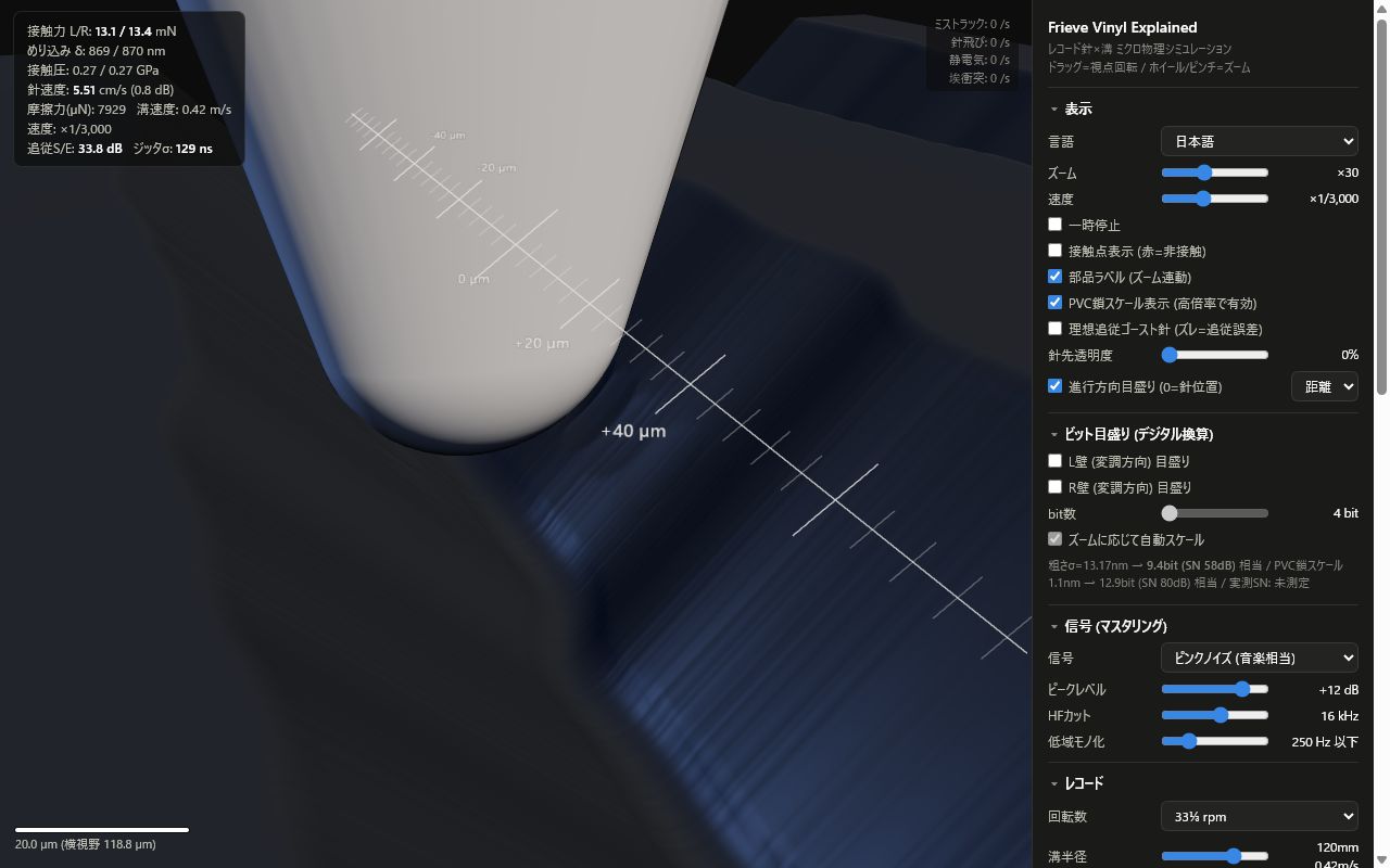
初回表示は、ブラウザの主言語が日本語の場合だけ日本語になります。表示パネルの言語設定からいつでも切り替えられます。
概要
このアプリは、マスタリング信号が溝壁の変位になり、針が接触して出力へ変換されるまでの流れを可視化します。表示や設定値は実スケールと実単位を基準にしているため、抽象的なアニメーションではなく、レコードやカートリッジの条件を変える感覚で操作できます。
表示上の誇張は、ズームとスローモーションによるものです。針、溝、埃、接触マーカー、ビット目盛り、測定グラフは同じシミュレーション状態を参照しています。
アプリを起動
英語 UI で開く場合:
特徴
- 45/45 方式のレコード溝を針がトレースする様子をリアルタイム 3D 表示。
- 溝全体の動きから、表面粗さのナノメートル領域まで拡大可能。
- ピンクノイズ、正弦波、無音溝を切り替え可能。
- 回転数、溝半径、表面粗さ、埃、傷、静電気を調整可能。
- 針形状、針先半径、針圧、チップ質量、コンプライアンスを調整可能。
- 理想的にトレースした場合のゴースト針で、トラッキング誤差を視覚化。
- 溝壁変位をデジタル量子化ステップと比較するビット目盛り。
- 周波数特性、ノイズスペクトル、S/N、相当ビット数、THD、ミストラック率、針飛び率の測定。
主な操作
表示
Zoom で、溝全体、針の接触、盤面粗さ、分子スケールの目安まで拡大できます。Speed はスローモーション倍率です。Pause を有効にすると、その時点の状態を止めて観察できます。
信号
Pink noise は音楽に近い信号、Sine wave はテストトーン、Silence は盤面ノイズの観察向けです。ピークレベル、高域カット、低域モノラル化で溝の変調が変わります。
レコード
回転数と溝半径は溝速度に影響します。表面粗さ、埃、傷、静電気は、針の動きや測定結果に現れる再生ノイズやトラブルを変化させます。
針 / カートリッジ
楕円針と丸針を切り替え、針圧、チップ質量、コンプライアンスを調整して、トラッキング安定性や高域特性の変化を確認できます。
ビット目盛り
L 壁または R 壁の目盛りを表示すると、アナログの溝変位をデジタルのステップ幅と比較できます。Auto-scale は現在のズームで読みやすいビット数を自動選択します。
測定 / 解析
Run Measurement は、現在の設定で短いオフライン測定を行います。周波数特性、ノイズ、S/N、相当ビット数、THD、ミストラック、針飛びの結果が表示されます。
表示の読み方
- 接触マーカーが緑なら溝壁に接触中、赤なら接触を失っています。
- ゴースト針は理想トレース位置です。実際の針とのズレが大きいほど、トラッキング誤差が大きいことを示します。
- 埃、傷、静電気は 3D 表示上の乱れとして現れ、出力グラフにも影響します。
- 進行方向の目盛りは、選択したモードに応じて時間または距離を表示します。
技術的背景
カッティング: 信号から溝へ
このシミュレーションは、ステレオ LP の標準的な 45/45 方式を前提にしています。レコード溝は 90 度の V 字溝として扱い、左右チャンネルはそれぞれ左右の溝壁の法線方向変位として記録されます。再生時には、針の動きを 45/45 の逆変換で L/R 出力に戻します。
溝形状に大きく関わる信号処理は、次のように扱っています。
| 項目 | モデル |
|---|---|
| 音源 | ピンクノイズ、正弦波、無音。ピンクノイズは、マスタリング処理後に正規化し、レベル比較しやすくしています。 |
| 低域制御 | 20Hz のランブル用ハイパスでサブソニック成分が溝変位を支配しないようにし、80Hz の音楽相当低域整形でマスタリング済み音源に多い長期的な低域ロールオフを表します。 |
| 低域モノラル化 / エリプティック EQ | M/S 処理で低域の S 成分を抑え、低音をほぼモノラルに近づけます。これにより過大な上下方向の溝変位を抑えます。 |
| 高域制限 | 既定 16kHz のマスタリング用ローパスで、短波長の溝変調量を制御します。 |
| RIAA 録音 EQ | カッティング前に高域を持ち上げ、低域を抑える録音カーブを適用します。再生時には対応するディエンファシスを適用します。 |
| 速度から変位へ | レコードのカッティングは速度基準ですが、画面に見える溝は変位です。速度信号を積分して壁面変位に変換し、ソフトリミッタを経て、壁面変位の上限をおよそ +/-25um に制限します。 |
| 基準レベル | 0dB は壁方向ピーク速度 5cm/s として扱います。既定のピンクノイズレベル +12dB は、LP 音楽として高めだが現実的なピークを想定しています。 |
このため、低域は大きな変位として、高域は短い波長の壁面変調として見えます。また、ステレオ低域が上下方向の溝運動に影響することも確認できます。
溝面、粗さ、ノイズ
溝面は完全な平滑面ではありません。このモデルでは、粗さを 3 つの長さスケールの合成として扱います。
| スケール | 相関長 | 何を表すか |
|---|---|---|
| 微細粗さ | 0.15um | 分子塊や PVC 微結晶スケールの凹凸。 |
| 中間粗さ | 2um | スタンパー転写誤差や局所的なプレス面のテクスチャ。 |
| うねり | 30um | 溝方向に続く、より長い面の揺らぎ。 |
ただし、針は画面に見える粗さをそのまま感じるわけではありません。接触パッチはおよそ 5x7um あり、高い接触圧で PVC の微小凸部は押し潰されたり平均化されたりします。そのため、表示される粗さと針が実際に感じる粗さは分け、非常に短い波長の成分は針の運動へ入る前に弱めています。
既定の粗さ sigma は 13.17nm です。このモデルでは、5cm/s 基準で約 60.0dB の S/N、つまり約 9.7bit 相当に対応します。既定の音楽ピーク +12dB と合わせると、有効なダイナミックレンジは約 72dB です。これは実測されるレコード再生の上限域、および AFM で観察されるプレス溝粗さと同じオーダーを狙った値です。
埃、傷、静電気は別々の欠陥として扱います。
- 埃はランド上に残る、溝壁に付着する、V 溝底に落ちる、のいずれかとして発生します。針に実際に押された粒子だけが変形し、接触した場所に局所的な圧痕を残します。
- 傷は、横断方向の切れ込みと盛り上がったバリが混ざった損傷として扱います。切れ込みは接触喪失を起こし、バリはポップノイズや針飛びの原因になります。
- 静電気は、短い減衰を持つ電気的パルスとして出力に加えます。これは、静電気ノイズを機械的な溝変位ではなく、再生チェーンに現れる症状として扱うためです。
針と接触力学
針モデルは、溝断面内のチップ (x, y) とアーム (x, y) の 4 自由度です。カンチレバーのばねはカートリッジのコンプライアンスから決まり、既定の 15cu、針圧 2g では静的なたわみがおよそ 0.3mm になります。実効質量 12g のアームにより、アームとカートリッジの低域共振はおよそ 12Hz 付近に現れます。
接触力は、球面針の Hertz 接触と同じオーダーになるように調整した弾性基礎モデルで扱います。接触の減衰は Kelvin-Voigt 型の粘弾性項で、接触共振付近の PVC の損失を表します。
可視化で使う代表的な材料値と接触値は次の通りです。
| 量 | およその値 |
|---|---|
| PVC のヤング率 | 3GPa |
| PVC のポアソン比 | 0.4 |
| 有効弾性率 | 3.57GPa |
| 針圧 2g 時の壁あたり法線力 | 14mN |
| 接触圧 | 0.4GPa |
| めり込み量 | 0.9um |
| 接触共振 | 40kHz |
トレーシングロスやピンチ効果は、見た目だけの効果として足しているものではありません。有限の走査半径を持つ針先が、短く急な溝変調を完全にはなぞれないという幾何から生じます。高域、内周、丸針ではこの影響が大きくなります。
どちらかの溝壁との接触が約 30us を超えて失われるとミストラックとして数えます。針先の底がランド面より約 6um 以上持ち上がる、または横方向に溝から逃げると針飛びとして数えます。通常の音楽レベルでは、このモデルでの実質的な針飛び要因は傷です。
再生と測定
カートリッジ出力は針速度に比例します。アプリは壁面運動を 45/45 逆変換で L/R に復号し、RIAA 再生ディエンファシスをかけた上で、可聴帯域の測定を行います。
S/N は 5cm/s 基準に対し、20Hz-20kHz のノイズ RMS から算出します。相当 bit 数は、デジタルオーディオとの比較でよく使われる (SNR - 1.76) / 6.02 です。ビット目盛りはあくまで比較用の物差しであり、レコードが実際に量子化されているという意味ではありません。
THD は正弦波の高調波成分から測定します。ライブ HUD の追従 S/E は、理想的な溝変位と実際の針の追従誤差を比べる機械的な追従指標で、出力波形の SINAD ではありません。
参考になる代表値:
- 1kHz、5cm/s 正弦波の再生レベルは約 -0.02dB 以内で、既定モデルの THD は約 0.55% です。
roughSigma=13.17nmでは、ノイズ基準は約 60.0dB S/N、9.7bit 相当です。- 15kHz の球針再生では、半径 60mm 付近の内周は半径 146mm 付近の外周に対して約 11.9dB のトレーシングロスが出ます。
- 低すぎる針圧、高レベル 10kHz、内周再生の組み合わせではミストラックが起きますが、通常設定では安定します。
モデルの限界
これは物理可視化であり、レコードプレーヤー全体を完全に再現するシミュレーターではありません。主な簡略化は次の通りです。
- 主な力学モデルは溝断面内の 2 次元です。溝進行方向の針振動やスティックスリップ摩擦は詳細には扱いません。
- 粗さは溝方向に沿って変化します。横方向の接触パッチ平均化は解析的な係数で表します。
- 描画される溝壁は高さ場で、オーバーハングは含みません。
- ワウ、フラッター、偏心、盤の反り、カートリッジの電磁変換、容量、抵抗、フォノイコライザー側の電気負荷は対象外です。
- PVC 鎖スケール表示は、局所的な分子スケールの目安です。分子動力学シミュレーションや PVC 分子全体のランダムコイルモデルではありません。
注意
これは教育用の物理可視化です。主要な機械的関係は実単位で扱いますが、カートリッジ、溝面、再生チェーンを完全に再現するものではありません。